Thursday, September 3, 2020

STM32F103R6 SysTick And Digital Clock Example

SysTick is a timer bases on timer interrupt that regularly update its value. We can use it for generating timing delay. It run on background allowing the main program loop to do other tasks. In this example I will use this feature to create a 4-digit digital clock. It shows only MM:SS.
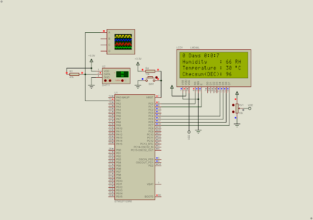
 

STM32F103R6 SysTick And Digital Clock Example
Simulating Program

It's free running as it's just an introductory example. Display type is common anode. It's just a simulation model in Proteus VSM. I'm not sure about the read physical device. Device's clock rate is 8MHz.

STM32F103R6 SysTick And Digital Clock Example
Device Configuration

I use STM32 HAL driver and code configuration wizard to write this program.

  1. /* USER CODE BEGIN Header */
  2. /**
  3.   ******************************************************************************
  4.   * @file : main.c
  5.   * @brief : Main program body
  6.   ******************************************************************************
  7.   * @attention
  8.   *
  9.   * <h2><center>&copy; Copyright (c) 2022 STMicroelectronics.
  10.   * All rights reserved.</center></h2>
  11.   *
  12.   * This software component is licensed by ST under BSD 3-Clause license,
  13.   * the "License"; You may not use this file except in compliance with the
  14.   * License. You may obtain a copy of the License at:
  15.   * opensource.org/licenses/BSD-3-Clause
  16.   *
  17.   ******************************************************************************
  18.   */
  19. /* USER CODE END Header */
  20. /* Includes ------------------------------------------------------------------*/
  21. #include "main.h"
  22.  
  23.  
  24. /* Private function prototypes -----------------------------------------------*/
  25. void SystemClock_Config(void);
  26. static void MX_GPIO_Init(void);
  27. /* USER CODE BEGIN PFP */
  28.  
  29. void ssdAssign(unsigned char _data);
  30.  
  31. const char dAnode[10] = {0xC0,0xF9,0xA4,0xB0,0x99,0x92,0x82,0xF8,0x80,0x90};
  32. unsigned char mark = 0x7F;
  33. volatile unsigned int secondCnt=0,msCnt=0,msSsd=0,minuteCnt=0;
  34.  
  35. /**
  36.   * @brief The application entry point.
  37.   * @retval int
  38.   */
  39. int main(void)
  40. {
  41.  
  42. /* Reset of all peripherals, Initializes the Flash interface and the Systick. */
  43. HAL_Init();
  44.  
  45. /* Configure the system clock */
  46. SystemClock_Config();
  47.  
  48. /* Initialize all configured peripherals */
  49. MX_GPIO_Init();
  50.  
  51. /*SysTick Configuration*/
  52. SystemCoreClockUpdate();
  53. /*Generate interrupt for 100 us*/
  54. SysTick_Config(SystemCoreClock/10000);
  55. SysTick ->CTRL=0;
  56. SysTick ->VAL=0;
  57. SysTick ->CTRL=(SysTick_CTRL_TICKINT_Msk //Enable SysTick Exception
  58. |SysTick_CTRL_ENABLE_Msk //Enable SysTick system timer
  59. |SysTick_CTRL_CLKSOURCE_Msk); //Use process clock source
  60.  
  61. /* USER CODE BEGIN WHILE */
  62. while (1)
  63. {
  64. switch(msSsd){
  65. case 0:
  66. GPIOB ->ODR = dAnode[secondCnt/10]&mark;
  67. GPIOB ->ODR |= GPIO_ODR_ODR13;
  68. break;
  69.  
  70. case 5:
  71. GPIOB ->ODR = dAnode[secondCnt%10]&mark;
  72. GPIOB ->ODR |= GPIO_ODR_ODR12;
  73. break;
  74.  
  75. case 10:
  76. GPIOB ->ODR = dAnode[minuteCnt/10]&mark;
  77. GPIOB ->ODR |= GPIO_ODR_ODR15;
  78. break;
  79.  
  80. case 15:
  81. GPIOB ->ODR = dAnode[minuteCnt%10]&mark;
  82. GPIOB ->ODR |= GPIO_ODR_ODR14;
  83. break;
  84.  
  85. }
  86. }
  87. /* USER CODE END 3 */
  88. }
  89.  
  90. void SysTick_Handler(void)
  91. {
  92.  
  93. HAL_IncTick();
  94.  
  95. if(uwTick>=10){
  96. msCnt+=1;
  97. msSsd+=1;
  98. uwTick=0;
  99. }
  100.  
  101. if(msCnt>=500){
  102. secondCnt+=1;
  103. msCnt=0;
  104. mark^=0x80;
  105. }
  106.  
  107. if(secondCnt>=60){
  108. secondCnt=0;
  109. minuteCnt+=1;
  110. }
  111.  
  112. if(minuteCnt>=60) minuteCnt=0;
  113.  
  114. if(msSsd>20) msSsd=0;
  115.  
  116.  
  117. }
  118.  
  119. /**
  120.   * @brief System Clock Configuration
  121.   * @retval None
  122.   */
  123. void SystemClock_Config(void)
  124. {
  125. RCC_OscInitTypeDef RCC_OscInitStruct = {0};
  126. RCC_ClkInitTypeDef RCC_ClkInitStruct = {0};
  127.  
  128. /** Initializes the RCC Oscillators according to the specified parameters
  129.   * in the RCC_OscInitTypeDef structure.
  130.   */
  131. RCC_OscInitStruct.OscillatorType = RCC_OSCILLATORTYPE_HSI;
  132. RCC_OscInitStruct.HSIState = RCC_HSI_ON;
  133. RCC_OscInitStruct.HSICalibrationValue = RCC_HSICALIBRATION_DEFAULT;
  134. RCC_OscInitStruct.PLL.PLLState = RCC_PLL_NONE;
  135. if (HAL_RCC_OscConfig(&RCC_OscInitStruct) != HAL_OK)
  136. {
  137. Error_Handler();
  138. }
  139. /** Initializes the CPU, AHB and APB buses clocks
  140.   */
  141. RCC_ClkInitStruct.ClockType = RCC_CLOCKTYPE_HCLK|RCC_CLOCKTYPE_SYSCLK
  142. |RCC_CLOCKTYPE_PCLK1|RCC_CLOCKTYPE_PCLK2;
  143. RCC_ClkInitStruct.SYSCLKSource = RCC_SYSCLKSOURCE_HSI;
  144. RCC_ClkInitStruct.AHBCLKDivider = RCC_SYSCLK_DIV1;
  145. RCC_ClkInitStruct.APB1CLKDivider = RCC_HCLK_DIV1;
  146. RCC_ClkInitStruct.APB2CLKDivider = RCC_HCLK_DIV1;
  147.  
  148. if (HAL_RCC_ClockConfig(&RCC_ClkInitStruct, FLASH_LATENCY_0) != HAL_OK)
  149. {
  150. Error_Handler();
  151. }
  152. }
  153.  
  154. /**
  155.   * @brief GPIO Initialization Function
  156.   * @param None
  157.   * @retval None
  158.   */
  159. static void MX_GPIO_Init(void)
  160. {
  161. GPIO_InitTypeDef GPIO_InitStruct = {0};
  162.  
  163. /* GPIO Ports Clock Enable */
  164. __HAL_RCC_GPIOB_CLK_ENABLE();
  165. __HAL_RCC_GPIOA_CLK_ENABLE();
  166.  
  167. /*Configure GPIO pin Output Level */
  168. HAL_GPIO_WritePin(GPIOB, GPIO_PIN_0|GPIO_PIN_1|GPIO_PIN_2|GPIO_PIN_12
  169. |GPIO_PIN_13|GPIO_PIN_14|GPIO_PIN_15|GPIO_PIN_3
  170. |GPIO_PIN_4|GPIO_PIN_5|GPIO_PIN_6|GPIO_PIN_7, GPIO_PIN_RESET);
  171.  
  172. /*Configure GPIO pins : PB0 PB1 PB2 PB12
  173.   PB13 PB14 PB15 PB3
  174.   PB4 PB5 PB6 PB7 */
  175. GPIO_InitStruct.Pin = GPIO_PIN_0|GPIO_PIN_1|GPIO_PIN_2|GPIO_PIN_12
  176. |GPIO_PIN_13|GPIO_PIN_14|GPIO_PIN_15|GPIO_PIN_3
  177. |GPIO_PIN_4|GPIO_PIN_5|GPIO_PIN_6|GPIO_PIN_7;
  178. GPIO_InitStruct.Mode = GPIO_MODE_OUTPUT_PP;
  179. GPIO_InitStruct.Pull = GPIO_NOPULL;
  180. GPIO_InitStruct.Speed = GPIO_SPEED_FREQ_HIGH;
  181. HAL_GPIO_Init(GPIOB, &GPIO_InitStruct);
  182.  
  183. }
  184.  
  185. /* USER CODE BEGIN 4 */
  186.  
  187. /* USER CODE END 4 */
  188.  
  189. /**
  190.   * @brief This function is executed in case of error occurrence.
  191.   * @retval None
  192.   */
  193. void Error_Handler(void)
  194. {
  195. /* USER CODE BEGIN Error_Handler_Debug */
  196. /* User can add his own implementation to report the HAL error return state */
  197. __disable_irq();
  198. while (1)
  199. {
  200. }
  201. /* USER CODE END Error_Handler_Debug */
  202. }
  203.  
  204. #ifdef USE_FULL_ASSERT
  205. /**
  206.   * @brief Reports the name of the source file and the source line number
  207.   * where the assert_param error has occurred.
  208.   * @param file: pointer to the source file name
  209.   * @param line: assert_param error line source number
  210.   * @retval None
  211.   */
  212. void assert_failed(uint8_t *file, uint32_t line)
  213. {
  214. /* USER CODE BEGIN 6 */
  215. /* User can add his own implementation to report the file name and line number,
  216.   ex: printf("Wrong parameters value: file %s on line %d\r\n", file, line) */
  217. /* USER CODE END 6 */
  218. }
  219. #endif /* USE_FULL_ASSERT */
  220.  
  221. /************************ (C) COPYRIGHT STMicroelectronics *****END OF FILE****/
  222.  

Click here to download its source file. 


For other similar posts please check,

  1. Getting Started With STM32F103C8T6 Module with STM32CubeIDE
  2.  STM32F103C8T6 Blue Pill SysTick and Multiplexing Display Example
  3.  STM32F103C8T6 Blue Pill Switch And Multiplexing Display Interface Using SysTick
  4.  STM32F103C8T6 Blue Pill SysTick LED Blinking
  5. STM32F103R6 Common Anode Seven Segments Display Example 
  6. STM32F103R6 Common Anode Seven Segments Display And Switch Interfacing 
  7. STM32F103R6 Simple 2-Digit Multiplexing Display And Switch Example 
  8. STM32F103R6 SysTick And Digital Clock Example 
  9. STM32F103R6 SysTick Two-Digit Multiplexing Display and Push Button


No comments:

Post a Comment